Home  >  Products  >  TeraView  >  EOTPR 4500
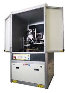
EOTPR 4500 Electro Optical Terahertz Pulse Reflectometry

Electro Optical Terahertz Pulse Reflectometry(EOTPR): The world’s fastest and most accurate fault isolation system.


The EOTPR 4500 system couples the EOTPR’s world leading sub-5 µm fault isolation accuracy with the next generation in automated probe stations. The purpose built auto prober has been designed to address the needs of today’s most advanced IC packaging technology, and can probe down to 5 µm pads on IC packages up to 150 mm x 150 mm in size.

EOTPR 4500


Key Features

• Purpose built auto prober for advanced IC packages.
• Can probe down to 5 µm pads on IC packages up to 150 mm x 150 mm.
• Availability of guided fully manual, semi-manual and automatic probing modes.
• Data acquisition of less than 5 seconds per pin.
• User interface software to manage recipe creation and data display.
• Sub-5 µm fault isolation accuracy.
• ODB++ file import for contact mapping and recipe generation with optional QuickView software.

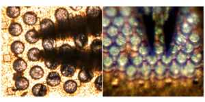
Needle-nose probe tip

Key Components

• IC package high precision auto-prober that supports the substrate size of 150 mm x 150 mm.
• In-built 3D line scan camera system to map contact locations and heights.
• EOTPR core unit.
• Optional DUT (device under test) heater supports up to 260°C.
• Optional DUT chiller supports down to -40°C.
• Optional needle nose probe tip to land on target as small as 5µm.


System Specifications

• Dimensions: 60 (w) x 132 (h) x 100 (d) cm
• Weight (approximate): 220 kg (core unit)
• Electrical Power Requirements: 90 VAC to 250 VAC, 47 to 63 Hz single phase
• Operating temperature: 18 °C (64 °F) to 30 °C (86 °F)


EOTPR Capabilities

• TDR pulse rise time: Less than 6 ps (based on processed data) defined as the time for the reflected impulse from the end of the high frequency probe to rise from 10 % to 90 % of its maximum value.
• Accuracy: Able to locate a feature on 50 Ω coplanar waveguide positioned close to the high frequency probe with precision of ± 5µm.
• Range: Up to 270 mm from contact with probe on a 50 Ω strip line.
• Input Impedance: 50 Ω nominal
• Channel Input Connector: 1 mm


Automated Probe Station

• Modes of operation: Full auto probing mode, semi auto probing mode, or guided manual probing mode (see specification below).
• Probe tip pitch: 50 μm to 1.2 mm
• Probe tip mount: Allows probe position to be adjusted in x, y, and z. Probe tip angle can be adjusted to ensure signal and ground tip co-planarity.
• Probe tip calibration Quick probe calibration to determine:
  • Position of the signal and ground tips.
  • Probe tip pitch.
• Device under test size: 5 mm x 5 mm to 150 mm x 150 mm
• Device mounting: DUTs are mounted to the probe station in a device specific fixture and held in place with vacuum. Reusable Gel-Pack mounts can be used for small samples.
• Optional device under test heater:
  • Enables a device under test mounted to the chuck to be heated to a maximum temperature of 260 °C
• Probe tip placement accuracy: +/- 0.5 µm
• Device under test contact type: Compatible with BGA, LGA and microbumps.
• Minimum solder ball diameter: 5 μm (manual mode), 30 μm (semi auto mode), 200 μm (full auto mode)
• Minimum LGA pad size:
  • 5 μm x 5 μm (manual mode)
  • 30 μm (semi auto mode)
• Device under test pre-scan time: 5 seconds per 9 mm wide stripe
  • <150 seconds to scan 140 mm x 140 mm DUT
  • <60 seconds to scan 70 mm x 55 mm DUT
  • <45 seconds to scan 40 mm x 25 mm DUT
• Dimensions: 150 (w) x 190 (h) x 150 (d) cm
• Weight (estimated): 250 kg
• Power Requirements: 1 x 110V to 250V, 10A, 50-60 Hz single phase