PM5 - Erickson Power Meters
The VDI Erickson PM5 Power Meter is a calibrated calorimeter-style power meter for 75 GHz to > 3 THz applications. It offers power measurement ranges from 1 µW up to 200 mW. The PM5 is the de facto standard for > 100 GHz power measurement. The sensor head has a WR10 input and VDI sells a variety of input waveguide tapers for use at
other frequencies.
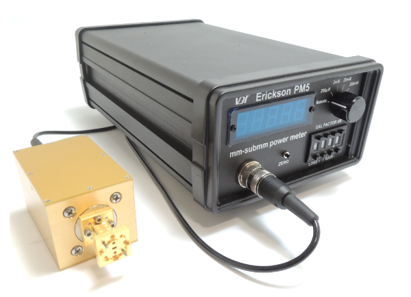
| Submillimeter Power Meter Model PM5 • Extremely wide bandwidth • Excellent input match • Low Noise • High Sensitivity • USB interface with open source software |
|
|
PM4 to PM5 Upgrade: A cost effective solution is available to upgrade existing PM4 units to achieve the full performance of the PM5. Upgrades of the PM3 systems are also available; however, although upgraded PM3 units will have improved performance, these may not achieve the full performance of a new PM5. Contact VDI for more details.
Measurements Above 110GHz: For measurements above the WR10 band (75-110GHz), VDI recommends purchasing waveguide tapers. Waveguide tapers transition from a smaller waveguide to a WR10 waveguide. The basic layout of this power measurement is:
[DUT] + [WRX.X to WR10 Taper] + [WR10 Waveguide on Power Meter] + [Power Meter]
The WRX.X denotes the waveguide band that best matches the output waveguide of the DUT.
Product Details: The PM5 is a waveguide dry calorimeter designed to be a primary standard for power measurements throughout the mm-submillimeter range. It is constructed with a waveguide load having a 6 second thermal time constant, and an excellent RF match. A thermal feedback circuit makes the sensor much faster (~0.1 sec TC) for most measurements. A calibration heater resistor is mounted on the load at nearly the same location that most of the input power should be dissipated. Very efficient coupling to the load may be made using standard linear tapers to any smaller waveguide band, and the response is fairly insensitive to the mode content. Input loss is minimized through the use of a very short waveguide.
The PM5 is similar to its predecessor the PM4, but
lower noise, improved
response, a USB interface instead of RS-232, and open source LabVIEWTM code. The range of the PM5 can be changed manually or by sending commands through the USB interface. The PM5 also offers an autoscaling feature that allows the range to be automatically changed depending on the input power level.
Additional Notes: 1. A 1 m cable connects sensor to the PM5. 2. The PM5 has four power ranges (200 µW, 2 mW, 20 mW, and 200 mW). 3. Auto scale mode allows for relatively rapid range changes (~30 seconds) compared with the normal ranges. The range will automatically change based on input power. For extremely low power measurements (<1µW), the Erickson PM5 should be used in normal (not auto scale) mode on the 200µW scale where low sensor drift is important. 4. A 1kΩ heater resistor (on the RF load) is used for DC calibration. Internal calibration check on all ranges. 5.The sensor has a thermal time constant (1/e) of 6 seconds. For faster response, the load is heated to a nearly constant temperature using a feedback loop. When input power is applied, the heater power is reduced, and the circuit measures the change, which is equivalent to the input power. The loop gain varies with the power to be measured, changing the response time. 6. VDI provides a one inch WR10 straight waveguide section attached to the WR10 sensor flange. The sensor flange can be easily stripped which requires the entire sensor head to be replaced. VDI recommends that the customer does not remove the one inch WR10 straight waveguide section from the WR10 sensor flange. | |


Copyright @ 2018 ACE. Solution Co., Ltd. 筑波科技股份有限公司 新竹生醫園區辦公室: 886-3-5500909 / 台元科技園區辦公室:886-3-5525633蘇州辦公室: 86-512-89188620;深圳辦公室: 86-755-29351095 電郵: service@acesolution.com.tw